This document introduces a set of useful diagram types and a subset of ArchiMate® elements.
Open & get the pdf version from this link. (Or just click the figure below to open the pdf.)

Check the ArchiMate User Community for more information: link
ArchiMate® Cookbook
1. Introduction
1.1 Purpose And Scope
This document covers ArchiMate® -patterns and examples, those of which can be used as ‘recipes’ and inspiration sources when modelling concepts and solutions related to the development work of an organization. ArchiMate® is a registered trademark of The Open Group
Almost all the business relevant behavioral and structural elements of an organization can be modelled with the ArchiMate®. ArchiMate® is a comprehensive and powerful notation, with a wide range of elements and relationships. However, only a subset of ArchiMate-elements and only a small set of diagram types are enough for most of the modelling purposes (80% of the cases). This document introduces the most useful diagram types and related ArchiMate-elements. This subset of ArchiMate-elements is grouped into the layers of ArchiMate® Framework (figure below).

Figure 1: ArchiMate® Framework.
The diagrams in this document are modelled according to ArchiMate® specification [1]. More ArchiMate -examples can be found from the blog [2]. This document is updated continuously, more interesting topics are to be added, and existing content is to be updated according to new information. This document (this link and the pdf) can be freely used and shared.
1.2 References
[1] ArchiMate® 3.2, Open Group, 2022. https://pubs.opengroup.org/architecture/archimate32-doc/.
[2] Enterprise Architecture at Work, 4th Edition, Marc Lankhorst et al., Springer, 2017.
[3] Mastering ArchiMate, Edition III, Gerben Wierda, 2017.
[4] Lean Enterprise Architecture Method For Value Chain Based Development In Public Sector, Hosiaisluoma et al, 2018. https://www.hosiaisluoma.fi/blog/lean-enterprise-architecture-method-for-value-chain-based-development-in-public-sector/
[5] ArchiMate Examples blog, Eero Hosiaisluoma. https://www.hosiaisluoma.fi/blog/archimate-examples/
[6] “Holistic Enterprise Development” blog, Eero Hosiaisluoma https://www.hosiaisluoma.fi/blog/
[7] Value analysis with Value Stream and Capability modeling, Christine Dessus, 2019 https://www.slideshare.net/chdessus/value-analysis-with-value-stream-and-capability-modeling
2. ArchiMate Diagram Types
2.1 Motivation View (Goals View)

A Motivation View (a.k.a. Goals View) can be used to depict why demand is meaningful: WHY this change is needed. With the Motivation View it is possible to model crucial drivers and root causes behind the demand, actual goals and related outcomes, as well as concrete requirements for further development. The Motivation View answers the questions to WHOM, WHY and WHAT. Whenever appropriate, a Value can be associated with the Motivation View, if it is important to illustrate the concrete benefits of the demand (development target).
This diagram type is modelled with ArchiMate® Motivation- and Strategy -elements.
2.1.1 Motivation View – Example

The Motivation View can be applied to many kinds of purposes, such as to depict a strategy of the whole organization or to define the business case or requirements of a single development target.
ArchiMate® Motivation- and Strategy -elements are quite self-descriptive when illustrated within the titled groups (as shown in the figure above). Diverse stakeholder groups (managers, process- and software developers etc.) can read the Motivation View without deep knowledge of ArchiMate®. As a result of this, the Motivation View is a very multipurpose diagram type. It would be important and valuable to create a Motivation View for each and every demand for change – before any (“build or buy”) actions are to be taken.
2.1.2 Risk Analysis View

Risk and Security View. Mapping of Risk and Security Concepts to the ArchiMate®. Security and data protection matters are part of risk management. This modelling approach covers them both.
This diagram type is modelled with ArchiMate® Motivation -elements.
References:
- How to Model Enterprise Risk Management and Security with the ArchiMate® Language, Open Group, DocumentNo: W172, 2017.
- Modeling Enterprise Risk Management and Security with the ArchiMate® Language, Open Group, 2015.
2.2 Business Model View
2.2.1 Business Model Canvas (BMC)

A Business Model Canvas (BMC) -diagram can be used for modelling a business model or a business case.
This diagram type is modelled primarily with ArchiMate® Business Layer -elements together with certain Motivation- and Strategy -elements.
2.2.2 SWOT Analysis View

A development target can be analyzed and depicted with the SWOT View -diagram. (SWOT stands for Strengths, Weaknesses, Opportunities and Threats.)
This diagram type is modelled with ArchiMate® Assessments -elements.
2.2.3 Value Stream View

A Value Stream diagram defines e.g. how value is created for the customers according to the Business Model. In addition, value stream modelling can be used to depict how the business capabilities are connected to the value stream. This makes it visible what is the role and meaning of each capability (and related resources), and what is the actual value-add of each capability in the overall end2end value creation stream (process). As such, the value stream description (with capability connections) visualizes both the beneficial and unproductive capabilities, when measured with pure value-creation factors. How an organization creates value for the customers, and with what capabilities.
A value stream focuses us to “start talking business value instead of architecture”. Architecture, in turn, defines the behavior and structure behind each capability.
This diagram type is modelled with ArchiMate® Strategy -elements. The Value Stream -element is introduced in the ArchiMate® 3.1 version link.
2.2.3.1 Value Stream – Example

The Value Stream (figure above) represents the Business Model (added with value elements), whereas the Business Process (figure below) represents the Operating Model (the implementation of the Value Stream). In that case, the value stream and process describe the same “thing”, but in different abstraction levels.

Figure 9: Relation of a Value Stream and a Business Process.
“A Business Model should also provide a very high-level view of the key parameters that together combine to produce the value proposition. An Operating Model explains the configuration of the enterprise resources considered optimal by the leadership team for the realization of the business model. In other words, how will the business model be realized by some suitable combination of People, Process, and Technology (PPT)”. [Ed Walters, Modeling the Business Model Canvas with the ArchiMate® Specification, Document No.: W195, Published by The Open Group, May 2019.]
The topic of value stream analysis is covered in more detail by Christine Dessus in “Value analysis with Value Stream and Capability modeling” (see [8] ).
2.2.4 Strategy & Capability View

For the successful and efficient operational development of an organization, it is crucial that the strategy and strategic goals can be connected to the Business Model, to the Capability Model, to the Operating Model, and preferably to all the development targets.
The strategy can be modelled with ArchiMate® Strategy -elements: Course of Action, Capability and Resource. With these elements, the organization can be analyzed and depicted according to Resource-Based View (RBV) -approach.
Figure 10: Strategy – Pattern.
A Capability Map View, the Capability Model, is valuable to identify the following:
- the strategic core capabilities, which constitute the fundaments of the existence of the organization (incl. value creation, competitive advantage), and
- the basic capabilities, which enable the daily operations of the organization.
For capability assessment and identification, the following can be considered:
- a capability defines WHAT the organization does (whereas a resource defines HOW),
- a capability is unambiguous (no overlaps), and relatively stable by its nature,
- a capability can be divided into more detailed, lower-level capabilities,
- a capability can be grouped into a capability group,
- a capability can be:
- organizational (intangible, related to the existence, strategy or value creation of an organization) or
- operational (produced by tangible or intangible resources, related to the operating model).
For more details see Business Capability.
2.2.4.1 Capability Map View

A Capability Map View is modelled with ArchiMate Capability -elements. Capability Groups can be modelled with either Capability- or Group-elements.
2.2.4.2 Strategy & Capability Planning View

Figure 12: Strategy & Capability Planning View – Example (ref. “Strategy to Capability” Value Stream).
The Strategy View & Capability Planning View is modelled with ArchiMate Motivation- and Strategy-elements (figure above). This view and these elements can be used for Capability-Based Planning (CBP) purposes.
2.2.4.3 Strategy To Capability View

Figure 13: Strategy To Capability View – Example.
Another example of how Capability-Based Planning (CBP) can be supported by modelling. Capabilities can be identified based on the strategic course of actions, which can be derived from strategic goals and -outcomes.
For the sake of enabling strategy execution in practice, the strategy statements should be expressed as imperatives, actionable clearly stated clauses. These imperative actions can be modelled with ArchiMate Course of Action -elements. A suggested form is used imperatively as follows: “Focus on Customer Experience”, “Automatize Biz Processes”, “Establish Demand Management virtual team” etc.
2.2.4.4 Capability Planning View

Figure 14: Capability Planning View.
This view can be used for designing the actual architectural building blocks to realize a capability. The Grouping -element can be used for aggregating the elements into a logical entity.
See Capability-Based development for more details.
2.2.5 Implementation Roadmap View

This view can be used for modelling the implementation plan of a strategy or capability etc.
An implementation roadmap can be added with the core enterprise architecture elements (such as application services) that are to be implemented in certain phases as illustrated in the figure below.

This version (figure above) can be used for grouping the changes into the implementation phases.
2.3 Layered View

Figure 17: Layered View (Overview) – Basic Design Pattern.
The Layered View combines ArchiMate-elements from different ArchiMate-layers as follows: Business-, Application- and Technology Layers.
The Layered View enables the development target to be analyzed and depicted as a layered “stack” as follows: first the business aspects on the top, then application aspects in the next layer, and finally the technology aspects on the bottom. This approach makes the overall big picture visible with all the necessary relationships between all the behavioral and structural elements, which are meaningful in the context of the development target in hand.
The layers are connected with the services (of different kinds), so in that sense, the Layered View is enabling the Service-Driven Approach (SDA) to analyze and depict a development target. This diagram type is one of the most useful and informative, because that makes it possible to visualize all the important relationships from bottom-up and top-down between all the necessary elements on each layer (biz, app, tech).
This diagram type can be modelled with any elements of the ArchiMate layers.
2.3.1 Layered View – Business- and Application Layers Example

Figure 18: Layered View Example – business and application layers.
This example diagram of the Layered View connects business and application layers via the application services.
2.3.2 Layered View – Business Layer

Figure 19: Layered View, Business Layer – Design Pattern. Note: business interfaces as “channels”.
The Layered View can be applied to what is appropriate for the purpose. For example, layers can be left out and depict the development target from a certain viewpoint, e.g. from the business point of view like in the figure above. However, the layered approach is always based on the top-down order of the elements: customers on the top, then the business services and so on.
2.3.3 Layered View – Customer Service Journey

Figure 20: Customer Service Journey – Design Pattern.
The Layered View can also be taken from the customer viewpoint. Customer-centric diagrams can be modelled as Customer Service Journey or Service Blueprint diagrams. These diagram types combine the customer- and organization viewpoints together. These are the “outside-in” and “inside-out” approaches.
2.3.3.1 Layered View – Customer Journey View – Example

Figure 21: Customer Service Journey – Example.
The Customer Service Journey is a specialization of the Layered View, which combines business- and application layer elements.
2.3.4 Layered View – Swimline Process View

Figure 22: Extended Swimline View – Example.
This version represents the business roles as “swimlanes”, analogous to process modeling in BPMN.
2.3.4 Layered View – Service Design View

Figure 23: Service Design View – Design Pattern.
This version (above) of the Layered View using “swimline style”, is focused on customer role. This view can be used for service design purposes, for integrating “outside-in” and “inside-out” approaches into one view. The customer journey path is represented as a top layer, whereas the intra-organizational layers are represented next to the customer “swimline”. The bottom layers consist of applications and application services (which makes this view much more informative than a pure process diagram that can be modelled with the BPMN). As such this is a comprehensive view of a development target, a customer journey, a service (area) overview, process area, operational view of a value stream etc.
In this example above, Business process steps are performed by distinct business roles. Practically, business roles A, B and C are assigned to business process elements with ArchiMate Assignment-relationship type. Business role -elements are visualized as large objects that represent the “swimlanes”, and then the business process -elements are “nested” into those business roles. This modelling style saves space and minimizes crossing lines.
This version of the Layered View combines business layer elements and application layer elements. This cross-layer view can be used for modelling high-level process flow, to which application services and/or applications are linked to. With this view, a business process can be illustrated at a high level with ArchiMate – without the need for BPMN modelling. In addition, this view enables connecting process steps to actual application services used.

Figure 24: Service Design View – Design Pattern.
This version splits the customer journey with phases (Pre-service period, Service period and Post-service period) is added into the customer role, and channels added in between customer and personnel roles.
Business Process -elements are nested into Business Role -elements, which means that Business Roles are assigned to Business Processes (in the model repository). Hence, there are relations between these elements, even though they are not visible. This layout of the element saves space in the diagram. The value of this view is that we can use ArchiMate and its relations when visualizing a “swimlines of roles with connected application services and applications.
The service layer can be divided into distinct business services, if that is the case. Whether there is a certain specific business service that is to be designed, or there are several business services with specific channels that are serving the customer role. However, the focus is on the customer service path – or the customer journey, the customer perspective. As such, this approach is focusing on the outside-in approach, by linking the inside-out behavior and structure to customer-facing process steps.
2.3.5 Layered View – Service Blueprint – Example

Figure 25: Service Blueprint – Example.
This version reflects the Service Design tool Service Blueprint, which is based on a layered approach that consists of a) customer-facing and b) intra-organizational parts. The Service Blueprint can be easily modelled with the ArchiMate elements as shown above. This diagram can be used as a bridging tool (missing link) between the Service Design and Enterprise Architecture Management (EAM) practices.

Figure 26: Service Blueprint as a Layered View.
2.4 Interaction View (Co-operation View)
There are three variants of the Interaction View diagram type as follows:
- Actor Interaction View,
- Process Interaction View and
- Application Interaction View.
The Interaction View (also known as Co-operation View or Integration View) can be used for modelling relationships between the actors, processes or applications. The main advantage of this diagram type is to visualize the direction of switching information, and to illustrate the amount of the interacting elements. This diagram type has been found very informative and the easiest way to visualize the complexity of the development target.
This diagram type is to be used for modelling WHAT information flows in WHICH direction, from WHERE to WHERE. This diagram type is not applied for modelling the “dynamics” of the information switching: which element starts the interaction or what interfaces are used.
The ArchiMate Flow-relationship type is used here to model the information flow between the elements. The “information” can also be modelled as ArchiMate Business Objects or Data Objects.
2.4.1 Actor Interaction (Co-operation) View

Figure 27: Actor Interaction (Co-operation) View – Design Pattern.
2.4.2 Process Interaction (Co-operation) View

Figure 28: Process Interaction (Co-operation) View – Design Pattern.
2.4.3 Application Interaction (Co-operation) View

Figure 29: Application Interaction (Co-operation) View – Design Pattern.
This version of this diagram type is used for modelling application integrations at a high level: what data flows from which application to which application, in which direction. For more detailed level integration modelling these diagrams can be added with e.g. application interfaces or -services, and Trigger-relationships (see appendix 2).
2.5 Process View

Figure 30: Process View – Example.
Process View is modelled with ArchiMate Business Layer -elements as follows: Business Process), Business Actor), Business Role, Business Object and Business Event. Relationship types are Trigger and Access.
2.5.1 Business Process Functional Decomposition View

Figure 31: Business Function View – A process may span multiple business functions.
“A business function represents a collection of business behavior based on a chosen set of criteria (typically required business resources and/or competencies), closely aligned to an organization, but not necessarily explicitly governed by the organization.” [1]
A business function view can be used when it is necessary to model high-level business behavior, which groups more detailed behavior (such as processes). A business function is a behavioral element, which is performed by a structural element, typically by an organizational unit (e.g. department or group). A business function is a meaningful behavior for the organization. Business functions can be used for dividing the business into parts, each of which has certain logical cohesion based on the business services they provide.

Figure 32: Business Process Map with Function-Based Decomposition.
A business process map can be defined based on functional decomposition (figure above). Note! Business units are shown here just to illustrate the typical mapping between business functions and business actors. Business actors may not necessarily be shown in actual business process maps.
Examples of business functions are e.g. as follows: Finance and Accounting, Human Resources (HR), Procurement (Buying/Purchasing), Legal, Customer Service, Property Management. A business function is close to business capability, but they define business behavior in different abstraction levels: a business function represents business behavior in the operating model level, whereas a business capability represents business behavior on the business model level.
For more detailed discussion covering the relation of business processes and business functions, see Gerben Wierda’s book Mastering ArchiMate III [3].
2.6 Conceptual Data Model View
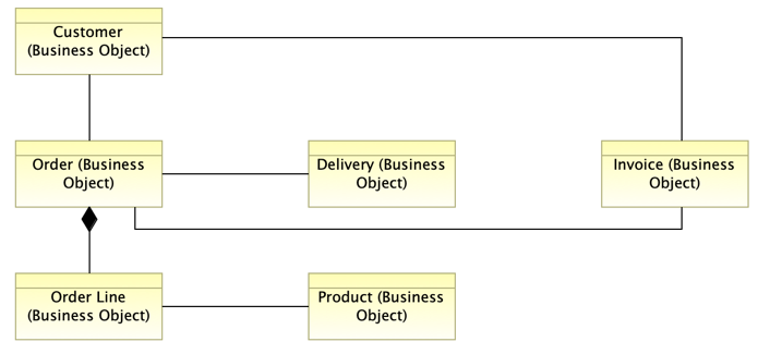
Figure 33: Conceptual Data Model View – Example.
The Conceptual Data Model View can be used for modelling the concepts and their relations of the development target.
This diagram type is modelled with ArchiMate Business Object -element and Association, Composition, Aggregation and Specialization relationship types. Some tools allow cardinality indicators (such as “one”, “many”, “0..n”) to be modelled on both ends of the association relations between the elements.
2.7 Data Model View
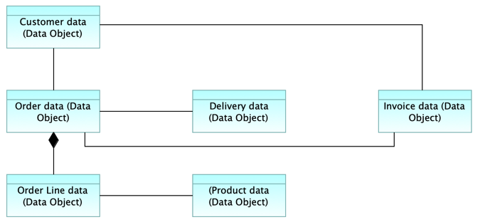
Figure 34: Data Model View – Example.
The Data Model View can be used for modelling the detailed, logical application-level information and their relations of the development target.
This diagram type is modelled with ArchiMate Data Object -element and Association, Composition, Aggregation and Specialization relationship types. Some tools allow cardinality indicators (such as “one”, “many”, “0..n”) to be modelled on both ends of the association relations between the elements.
2.8 Technology Platform View (Infrastructure View)

Figure 35: Technology Platform View – Design pattern.
The Technology Platform View (Infrastructure View) can be used e.g. for modelling the underlying infrastructure and deployment of an application (software, servers, clustering, communication networks, load balancing etc.).
This diagram type is modelled with ArchiMate Technology layer elements such as Node, Technology Service, Artifact, Device, System Software, Technology Interface and Communication Network.

Figure 36: Technology Platform – Example.
2.9 Application Structure View (Solution Architecture)
The Solution Architecture defines the behavior and structure of a single solution, which is a part of the Enterprise Architecture (EA). A solution is a logically and physically independent, autonomous building block of the organization-wide EA. In the EA, a solution is a “black box”: its interfaces and services are interesting, but its internal structure is irrelevant. As such, a solution is the smallest meaningful unit of EA. A solution can also be comprised as a “system”, whereas EA is a “system of systems”. Systemic thinking takes the holistic view by identifying and considering all the aspects of business, application and technology.
Solution Architecture, instead, covers the application as a “white box”: its internal structure and interfaces with adjacent applications are interesting. The solution architecture comprehends the internal structure of an application: the modularization (sub-components and their services/interfaces and dependencies). In addition, the solution architecture typically takes the technology aspect into account – in the form of a “technology platform”.
2.9.1 Application Design Pattern (Basic Model)

Figure 37: Application View – Design Pattern (Basic Model).
Solution Architecture modelling can be done with the elements of ArchiMate Business, Application and Technology layers. The logical view of the structure of a solution is modelled with ArchiMate Application layer elements such as Application Component, Application Service, Application Interface, Application Process and Application Function.
The logical structure of a solution is modelled with ArchiMate Application Component -elements. The internal behavior of an application is modelled with the Application Process and Application Function -elements. Provided services and interfaces (to adjacent solutions) of an application are modelled with Application Service and Application Interface -elements. The Application Interface -element is used for modelling the user interfaces (GUIs) and app2app interfaces (APIs).
According to ArchiMate derivation rules (introduced in the ArchiMate specification), the basic application design pattern can be depicted as shown below.

Figure 38: Application View – Design Pattern (Simplification of the Basic Model).
Note! Application services and application interfaces are the “different sides of the same coin”: a) behavioral services and b) structural interfaces. Both can be used for modelling the behavior of an application that is exposed for external use (interactions). Which one to use depends on the case. Application services can be used for modelling functional dependencies and interactions. Application interfaces instead, can be used for modelling concrete user interfaces (GUIs) or app2app interfaces (APIs) with operations. As such, application interfaces can be used for modelling actual dynamics between applications, or between users and applications.
If an application interface is to be modelled instead of an application service, then the application interface is connected with the application component with a Composition -relation type (figure below).

Figure 39: Application Component and (provided) Application Interface.
GUI = Graphical User Interface, API = Application Programming Interface, both interfaces of an application. The former provides application services to the users, whereas the latter provides application services to other applications. According to ArchiMate specification: “An application interface represents a point of access where application services are made available to a user, another application component, or a node” [1].
2.9.2 Application Logical Structure View (Application Structure / Internal Structure)

Figure 40: Application Logical Structure (functional decomposition into sub-components /modularization).
This view is useful in designing or understanding the main structure of an application and its sub-components and the associated data. This diagram can be used e.g. to break down the structure of the application system under construction, to illustrate modularization /decomposition: what are the sub-systems / sub-components what are the application services (or application interfaces) they provide. The sub-components are nested into the main component (Aggregation relationship).

Figure 41: Application Logical Structure: sub-components and application services.
This view is useful in designing or understanding the main structure of an application, its sub-components and their functions. This diagram can be used e.g. to break down the structure of the application system under construction, to illustrate modularization (functional decomposition): what are the sub-systems / sub-components, what are the functions and application services (or application interfaces) they provide.

Figure 42: Application Logical Structure: Application Functions assigned to modules of an application (A).
Note! The behavior (functions) of an application can be modelled with either ArchiMate Application Function or Application Process -elements. The latter can also be used for modelling e.g. Robotic Process Automation (RPA) behavior.
2.9.3 Component Model (CM)
Application Component Model 0-n (CM 0-n) is an application architecture modelling approach, which consists of diagrams of different abstraction levels as follows:
- At Component Model 0 (CM-0) -level the diagram describes how the application interacts with its environment, what are the boundaries and interactions with adjacent applications and users. The target application is depicted as a black box.
- At Component Model 1 (CM-1) -level the diagram describes how the target application is decomposed into modules (main components), their responsibilities, and what application services (or application interfaces) those modules provide and require. The logical decomposition of an application is based on the functional aspects, which typically relates to physical decomposition too. The target application is depicted as a white box.
- At Component Model 2 (CM-2) -level, the diagrams describe how the main modules are decomposed into sub-components, and what are their responsibilities, services or interfaces.
The Application Component Model (CM) diagrams below consist of application components and application services. Alternatively, application interfaces can be used instead of application services depending on the case. As always, it is important to utilize such a modelling style that is appropriate for the purpose, and model only those elements that are relevant in the context, to fit for purpose. (Note! Application in this context is analogous to solution or system.)
2.9.3.1 Component Model – 0 (CM-0)

Figure 43: Component Model – 0 (CM-0).
The target application ”A” introduced in the middle of the diagram as a “black-box”, with all the application services it provides, and with all the required services, realized by adjacent applications. This is the Enterprise Architecture (EA) level view of the application: its internal structure is not relevant, but its services are.
2.9.3.2 Component Model – 1 (CM-1)

Figure 44: Component Model – 1 (CM-1).
The target application ”A” opened as a “white-box”, with all its internal sub-components (modules) shown with the services they provide and require. This is the Solution Architecture (SA) level view of the application: its internal behavior and structure are interesting (incl. e.g. internal application components, application processes, application functions, and application services or application interfaces they provide and require).
2.9.3.3 Component Model – 2 (CM-2)

Figure 45: Component Model – 2 (CM-2).
One of the main components (“A-2”) of the application “A” opened in a more detailed diagram.
2.9.4 Database
A database is a meaningful unit in the overall enterprise architecture of an organization. E.g. “Client database” or “Customer database”, “Product database” etc. A logical database is a composition of all the tables of an application (e.g. “Customer table”, “Orders table”, “Invoices table” etc.), which altogether build up a database. A logical database can be modelled on the application layer with Application Component- or with Data Object-elements.
A logical database can be modelled on the application layer with a) Data Object- or b) Application Component-element. Which element to use, depends on what kind of database is in question: a) a passive structure or b) an active structure. Data Object is suitable for modelling the passive data itself: what is the data, how it is structured or composed (or aggregated) from other data objects, and what are the associations between these data objects. Application Component is suitable for modelling an active data structure that is capable of data management behavior such as data processing and/or data storing.

Figure 46: Modelling a logical database with ArchiMate Data Object.
A Data Object can be used for modelling for example a logical database, a database table, message structure (switched between applications) etc.
A Data Model View consists of database tables as shown below. (See also chapter 2.7 ).

Figure 47: Data Model View.
A logical database can be modelled also with the Application Component, given that the database is capable of performing data processing or data storing. In such a case, a database is part of an application: a logical component of an application. (Other modular parts/components of an application can be for example “the front-end application” and “the business logic application”).

Figure 48: Database as a component of an application system.
In addition, a database can be modelled with technology layer elements such as Node, Artifact or System Software. All in all, there are several ways to model a database, depending on the abstraction level, as shown in the figure below. It depends on the case, from which viewpoint a database is to be modelled, e.g. from the application viewpoint as a logical entity, from technology viewpoint as a physical construct etc.

Figure 49: Database modelling in different abstraction levels.
2.9.5 Application Integrations
2.9.5.1 Application Interface and Synchronic Request-Reply Design Pattern

This pattern illustrates the following system case:
The application “A” provides the application interface “A-1”, which is used by application “B”. The application “B” calls the interface “A-1” and transfers parameters within the request message, and gets the response back within the message structure “Data Object A-1”. The application “B” is the active party that initiates the interaction (information switching).
This view is modelled with dynamic relations of ArchiMate: Trigger and Flow.
For more detailed Application Integration Patterns, see Appendix 2 (8.2 ).
2.9.5.2 ETL-Process

Figure 51: ETL-process pattern.
This ETL-process (Extract, Transform, Load) pattern view is modelled with Application Process and Data Object -elements. An ETL-process read from the source table(s), performs some processing, and then writes to the target table(s) (figure above). The ETL-process can be assigned to the Application Component with Assignment-relationship (figure below).

Figure 52: ETL-process, tables and assigned application.
2.9.6 Sequence Diagrams
8.9.6.1 Application Component Sequence Diagram View
Sequence diagrams are not exactly in the scope of the ArchiMate (or EA), but instead, those are in the scope of the UML (and SA). However, we can use ArchiMate for modelling sequences of actions taken by e.g. Application Components as shown below.

Figure 53: Application Sequence View.
Dynamic relations “Trigger” and “Flow” can be used for modelling dynamics between application components. The layout of this view can be positioned analogously to the UML sequence diagram.
2.9.6.2 Application Component Sequence Diagram View 2
This version (diagram below) illustrates how ArchiMate can be used for modelling sequences of actions taken by internal parts of Application Components. The internal parts are such as a) behavioral processes or functions and b) structural sub-components. These are modelled with Application Process-, Application Function- and Application Component -elements. Those are shown here just as alternatives.

The flow of actions in this sequence diagram (above):
- Application Component A’s sub-process X sends a request message with parameter A to Application B.
- Application Component B’s sub-process B-1 receives the incoming request, and then calls (synchronously) Application Component C, in which Application Function Y receives the request, performs some actions and responds back.
- The Application Component B’s other sub-process B-2 sends a message with parameters to the Application Component D, and then receives an acknowledgment. The Application Component D contains a sub-component that executes the processing.
- Application Component A receives the response message from Application Component B.
As shown here, we can model quite complex integration mechanisms with a combination of these elements (Application Component, Application Process and Application Function and relations (Trigger, Flow). UML sequence diagram has its own specialized purpose in software design, but ArchiMate can be utilized for quite many modelling purposes – also in application design.
Application integration is one of the most important parts of enterprise architecture. That is why it is advantageous if we can model more detailed how applications switch data, and what are the interaction mechanisms used. A good source to dive into integration patterns, see “Enterprise Integration Patterns” -book, here is the link: https://www.enterpriseintegrationpatterns.com/ .
2.9.7 Application Integration Patterns

Figure 55: Application Integration Patterns.
2.9.8 Use Case View

Figure 56: Use Case View – Design Pattern.
ArchiMate can be used for modelling the use case diagrams. A business actor can be associated with application services, which represent the use cases of the target application. These application services are the functionalities of the target application, and they can be used in other diagrams (such as Layered View).
The intrinsic value of this approach: we can use ArchiMate throughout the design cycle. From the business requirements gathering phase to the further detailed design phase. The same language, the same tool. No need for switching between UML and ArchiMate, or from one tool to another. (Some tools support many notations such as ArchiMate, BPMN and UML, like Sparx EA for example.) Application services can be used when we initially define what the application should do, and how the user roles use the application, and then finally, these already identified application services can be used in later design phases within diverse diagram types.

Figure 57: Use Case Analysis Views.
Use Case analysis can be performed by the following steps:
- Use Cases are identified by using application services (analogous to UML Use Case Diagram)
- Relation types are changed from Association to Serving (optional step)
- Application is added to realize the application services (optional step)
- Elements are positioned on the Layered View layout.
The diagrams 1-4 above are just mentioned here for information. Diagrams 1 and 4 can be kept as part of the documentation of the target application (here: Application Component X).
2.9.8.1 Use Case View – Example

Figure 58: Use Case View – Example.
A use case can be depicted with a layered view (figure above). The main use case can be modelled as a Business Service, the flow of actions can be modelled with Business Process -elements, and the related system-level use cases (a.k.a. System Cases) can be modelled with Application Service -elements.
The diagram below just illustrates how we can use add-on visual elements to point which elements are identified as new or modified parts of the development target area (the problem domain).

Figure 59: Use Case View – Example 2.
Once again we can see how the layered view can be applied to diverse modelling needs (=“use cases”).
3. ArchiMate-Elements (subset)

Figure 60: Subset of ArchiMate-elements.
These ArchiMate-elements cover the most cases (80% of diagrams can be modelled with these elements).
The subset of ArchiMate -elements are introduced in the following tables (based on ArchiMate specification [1]). ArchiMate-elements are grouped into the following categories: active structure, behavior and passive structure. In addition, there are certain composite elements as follows: Grouping, Location and Product.
Active structure element can be regarded as a “subject”, behavior element as a “predicate” (verb”), and passive structure element as an “object”.
3.1 ArchiMate Motivation -Elements

3.2 ArchiMate Strategy -Elements

3.3 ArchiMate Business Layer -Elements

3.4 ArchiMate Application Layer -Elements

3.5 ArchiMate Technology Layer -Elements

4. ArchiMate Relationships

Figure 61: ArchiMate -Relationships.
ArchiMate relationship types are used for modelling a) structural- b) dependency c) dynamic and d) other relations between the elements ([1]). Relations are introduced in the following table.

5. Metamodel
5.1 Metamodel – Core

Figure 62: Metamodel – Core (with subset of ArchiMate core elements).
Note! The behavior of a structure element (such as Business Actor, Application Component or Node) can be modelled with Process or Function -elements on each layer. For the sake of simplicity, this figure introduces Process -elements on each layer, namely: Business Process, Application Process and Technology Process. Thus, Business Function, Application Function or Technology Function can be used when appropriate, accordingly.
This applies both to the core metamodel (figure above) and also to the full metamodel (figure below).
5.2 Metamodel – Full

Figure 63: Metamodel – Full.
6. Diagram Types
The essential diagram types that tackle most (80%) of the modelling requirements are as follows:
The most useful diagrams:
- Goals View [2.1]
- Layered View [2.3 ]
- Interaction View (Co-operation diagram) [2.4 ]
- Actor Interaction View (Actor Co-operation diagram) [2.4.1 ]
- Process Interaction View (Process Co-operation diagram) [2.4.2 ]
- Application Interaction View (Application Co-operation diagram) [2.4.3 ]
Also valuable diagrams:
4. Conceptual Data Model View [2.6 ]
5. Data Model View [2.7 ]
6. Technology Platform View (Infrastructure View) [2.8 ]
Additional diagrams:
- Process View [2.5 ]
- Business Model Canvas (BMC) [2.2.1 ]
- Service Blueprint [2.3.6]
These diagram types are introduced in this document.
6.1 Basic Views
| Basic Views (Diagram Types) | ||
| # | Name | Description |
| 1 | Motivation View | Analysis view of the concept incl. drivers, goals, outcomes etc. |
| 2 | Layered View | An overview (the context) of the concept. |
| 3 | Conceptual Data Model View | Conceptual model of business objects and their relations at high-level. |
| 4 | Actor Interaction View | Information flows between business actors (such as organizations). |
| 5 | Process Interaction View | Information flows between processes (the operating model). |
| 6 | Application Interaction View | Data flows between applications at high-level: the business view. |
| 7 | Application Integration View | Data flows between applications at a detailed level with the application interfaces, protocols etc. The Solution Architecture (SA) version of the Application Interaction View. |
| 8 | Application Structure View | The internal logical structure of an application, the Solution Architecture (SA). Incl. e.g. Component Model (CM) 0-n diagrams. |
| 9 | Technology Platform View | The technology platform of an application. |
6.2 Business Model Views
| Business Model Views (Diagram Types) | ||
| # | Name | Description |
| 1 | Business Model Canvas (BMC) | Template for developing new or documenting existing business models at one page. |
| 2 | SIPOC | Suppliers, Inputs, Process, Outputs, Customers -diagram can be used for defining elements common to all processes. This is an easy tool for analyzing the business case: what is the value the customer gets and how. |
6.3 Customer Views
| Customer Views (Diagram Types) | ||
| # | Name | Description |
| 1 | Customer Journey | |
| 2 | Service Blueprint | |
6.4 Maps
| Maps (Diagram Types) | ||
| # | Name | Description |
| 1 | Strategic Goals | Map of strategic goals of an organization or an organization unit / domain. |
| 2 | Principles | Map of development principles of an organization or an organization unit / domain. |
| 3 | Value Streams Map | Map of value streams of an organization or an organization unit / domain. |
| 4 | Capability Map | Map of business capabilities of an organization or an organization unit / domain. |
| 5 | Resources | Map of resources of an organization or an organization unit / domain. |
| 6 | Business Actor Map | Map of business actors, internal and external to an organization or an organization unit / domain. |
| 7 | Business Service Map | Map of business services of an organization or an organization unit / domain. |
| 8 | Business Process Map | Map of business processes of an organization or an organization unit / domain. |
| 9 | Business Function Map | Map of business functions of an organization or an organization unit / domain. |
| 10 | Business Concept Map | Map of business concepts of an organization or an organization unit / domain. |
| 11 | Application Map | Map of applications of an organization or an organization unit / domain, grouped by certain business relevant criteria such as business service area. |
| 12 | Application Service Map | Map of application services of an organization or an organization unit / domain. |
| 13 | Data Object Map | Map of data objects of an organization or an organization unit / domain. |
| 14 | Technology Map | Map of technologies of an organization or an organization unit / domain. |
6.5 Solution Architecture Views
| Solution Architecture Views (Diagram Types) | ||
| # | Name | Description |
| 1 | Component Model | Decomposition of a solution into sub-components (modules, sub-systems). |
| 2 | Sequence Diagram | Information switching (method/procedure calls) between the components. |
| 3 | State Diagram | State machine: state transitions of a data object (e.g. class). |
Some of the Solution Architecture (SA) level diagrams are exactly the same as on the EA level. However, these diagrams mentioned in the table above are typical of the solution level. Diagrams 1 and 2 can be modelled with the Application Components.
7. Methods
7.1 Lean EA Framework (LEAF)
The Lean Enterprise Architecture Framework (LEAF) can be used for visualization of overall aspects from ideas to production. The idea behind this LEAF is to manage end-to-end value delivery chains of any kind of development targets, such as services. The LEAF consists of three layers as follows: 1) Management, 2) Value Delivery Chain and 3) Architecture Landscape – Operational Development.

Figure 64: LEAF – Level-1 (the business view).

Figure 65: LEAF – Level-2 (the EA content view).
The LEAF supports the BizDevOps -approach, in which business- and customer-driven demand- and requirements management is supported by architecture in the Design -phase. The Development and Operations -phases are aligned with the DevOps -approach. The Level-1 of the LEAF-framework consists of a management framework, business development framework, development framework and the EA content framework, which is grouped based on the organization-specific domain structure (e.g. business units, business service areas or operational value streams).
For more information see [3] and blog posts: https://www.hosiaisluoma.fi/blog/lean-ea-framework/ and https://www.hosiaisluoma.fi/blog/sparx-ea/ (a Sparx EA reference implementation).
7.2 Lean EA Development (LEAD)
The Lean Enterprise Architecture Development (LEAD) method is an integrated development operating model. The LEAD consists of the following aspects: 1) Value chain based Operating Model with revised EA practice and 2) Visualization tool supported Lean EA Framework, LEAF. The architecture function is participating in the work of the Demand Management team. This co-operation produces an architecture concept, which is then either accepted or rejected for further development (build or buy).

Figure 66: Value Chain based operating model with integrated EA discipline.
Within the LEAD, architecture is done “just enough”. Architecture artifacts (deliverables) are created on an on-demand basis, “just in time”, not “just in case”. All the architecture diagrams are published continuously on the EA portal for all the concerned stakeholders of the organization. Architecture is involved in all the development cases right from the beginning, there is no need for board committee reviews afterward. Architects provide the Architecture Landscape, against which all the development targets are evaluated before the development phase (build or buy). As the idea to production process performs daily basis (e.g. in two-week sprints), new architectural content is continuously added into the Architecture Landscape, which is managed within the EA tool’s repository.

Figure 67: The LEAD process (implementation of the “Idea To Production” Value Stream).
Note! The development phase consists of several “development paths”, some of which are introduced in the diagram above.
For more information of the LEAD see this blog post https://www.hosiaisluoma.fi/blog/lean-enterprise-architecture-method-for-value-chain-based-development-in-public-sector/.
The LEAD and the LEAF are introduced more detailed in the design science research article [3] (Lean Enterprise Architecture Method for Value Chain Based Development in Public Sector, Hosiaisluoma et al., 2018.), which can be retrieved from the Research Gate via this link: https://www.researchgate.net/publication/328560027_Lean_Enterprise_Architecture_Method_for_Value_Chain_Based_Development_in_Public_Sector .
You can get the pdf version of the article from this link.
7.3 Goal-Driven Approach (GDA)
Goal-Driven Approach (GDA) supports all kinds of development, by focusing on the WHY first of all (according to Simon Sinek’s “start with why” -concept). For every demand, it is always important to define the goals first, before any further actions are to be taken. It is crucial to analyze “to whom”, “why” and “what” and compose a clear one-pager of goals – for the sake of simplicity. If precise statements cannot be defined for defining drivers, goals and outcomes, then this implies that this demand is not clear enough, and that demand doesn’t deserve to be proceeded to detailed design or development phases.
The Goal-Driven Approach (GDA) is a simple approach to start with goals. This can be done by utilizing the Goals View -diagram type (introduced in this document). When the goals are clearly defined, then the demand can move forward in the value chain of the operational development operating model.

Figure 68: Goal-Driven Approach – start always with defining the goals (the WHY) first.
7.4 Service-Driven Approach (SDA)
Holistic enterprise development can be supported by the Service-Driven Approach (SDA), which focuses on services (instead of projects) as primary units of value creation, design, development and operations. The SDA combines both customer-oriented (“outside-in”) and organization internal behavior- and structure-oriented (“inside-out”) approaches. By focusing on services, enterprise development (or an IT function) can be organized as a “production line” that produces services. The service concept is crucial, everything can be provided and consumed as a service according to the idea where “everything is a service”.
The Service-Driven Approach (SDA) is based on layered approach, in which layers (business, application, technology) are connected with specific kind of services as follows: 1) business services, 2) application services and 3) technology services. All the development targets (demands) are analyzed and visualized with the services they provide and/or require. These layers and services are based on ArchiMate framework (figure below), which can be used for analyzing the behavior and structure of each development target – whether it is a single service or wider area such as a business unit.

Figure 69: ArchiMate Core Framework separates the elements of each layer in behavioral and structural aspects.
A simplified service-driven pattern is illustrated in the diagram below. These are the basic elements of Service-Driven Approach (SDA).

Figure 70: The core elements of the Service-Driven Approach (SDA).
The Service-Driven Approach (SDA) method starts from identifying the goals of the development target (the WHY) first. Then the concerning business service is analyzed e.g. as follows: WHAT are the customer groups and processes HOW the service is produced. In addition, WHAT are the application services, applications and technologies that are used (figure below).

Figure 71: Service-Driven Approach (SDA) method as a process.
The Service-Driven Approach (SDA) covers all the relevant aspects for analyzing and visualizing a business service. The method goes as follows:
- Identify Stakeholders, goals, outcomes, principles and requirements,
- Define Customers,
- Define Business service(s), to serve the customers
- Define Business process(es) & functions and related business actors, to realize the business service(s),
- Define Application services, to serve the processes & functions,
- Define Applications, to realize the app. services,
- Define Technology services (when appropriate), to serve the applications and
- Define Technology platforms (system softwares, servers, comm. networks etc.), to realize tech. services.
All of these elements can all be analyzed and visualized with the following diagram types (introduced in this document): Goals View-, Business Model Canvas-, Layered View- and Interaction View diagrams – depending on the case, and what is appropriate to fit for the purpose.
7.5 ArchiMate 1-2-3

Figure 72: ArchiMate 1-2-3.
ArchiMate 1-2-3 is a simple approach to utilize modelling within architecture work. This approach is based on the smallest possible set of ArchiMate elements (figure below).

Figure 73: ArchiMate 1-2-3 metamodel. The WHY and WHAT on the left, the HOW on the right
The naming “ArchiMate 1-2-3” stands for “one holistic wholeness, two aspects (behavior and structure), three layers (business, application, technology)”. It is analogous to and compatible with Goal-Driven Approach (GDA) and Service-Driven Approach (SDA), as they all are based on ArchiMate Framework’s layers and aspects.
The ArchiMate 1-2-3 is as easy as A-B-C, a fast track for start using modelling for visualization in all the development cases in an organization. By starting small and keeping things simple, and then learning by doing, this approach can be extended smoothly with other ArchiMate elements. Modelling can be used as a supporting method for overall development. Architecture artifacts can be created with an appropriate modelling tool, and all the concerning documents can be produced from the tool – according to Model-Based System Engineering, MBSE (as introduced in the SAFe). It is good practice to start small and simple, and then extend the way of working – as the architecture- and modelling maturity evolves. ArchiMate 1-2-3 is based on the same diagram types as introduced in this document.
7.6 EA Content Frameworks
There are three variations of how the EA content can be organized in the LEAF level-2 (introduced above) as follows: 1) Layered Framework, 2) Aspect-Oriented Framework or 3) Views & Maps Framework. These alternative approaches are based on the ArchiMate Core Framework, which consists of layers and aspects (figures 1 and 65).
7.6.1 Layered Framework

Figure 74: Layered Content Framework.
This is the conventional approach to manage the EA content within a layered view (according to ArchiMate Core Framework). Elements on the layers are positioned according to ArchiMate aspects as verticals. Note! These content placeholders (white boxes) can be named according to what is appropriate.
7.6.2 Aspect-Oriented Framework

Figure 75: Aspect-Oriented Content Framework.
This is the aspect-oriented approach to manage the EA content within a view with no layers (according to ArchiMate Core Framework).
7.6.3 Maps & Views Framework

Figure 76: Maps & Views Content Framework.
This is a “use case oriented” view to manage the EA content. This is a combination of a) typical diagrams grouped into the Views, and b) collection of maps of fundamental EA structural and behavioral elements. The maps are positioned according to ArchiMate aspects (active structure, behavior and passive structure).
Note! These frameworks are examples, all the content placeholders (white boxes) can be identified and named to what is appropriate; content placeholders can be added, modified, removed or replaced to according to what is essential in the organization. It is important to notice that these maps are collections (catalogs) of relevant elements in the enterprise architecture of an organization.
When customizing these content frameworks introduced here, the rule of thumb is to keep it simple. Good practice is to apply the Lean EA principles: use only the relevant content placeholders (“just enough”); create content placeholders only if needed (“just in time”) – not to create them “just in case”. However, content placeholders can act as reminders of what should be investigated and modeled. (A specific step-by-step method is to be introduced here.)
7.7 SIPOC (Suppliers, Inputs, Process, Outputs, Customers)
Six Sigma tool called SIPOC (Suppliers, Inputs, Process, Outputs, Customers) can be used for defining elements common to all processes. This is an easy tool for analyzing the business case: what is the value the customer gets and how.

Figure 77: SIPOC diagram.
7.8 EA Content – Views and Maps
7.8.1 Views
| Views (Diagram Types) | ||
| # | Name | Description |
| 1 | Goals View | Analysis view of the concept incl. drivers, goals, outcomes etc. |
| 2 | Layered View | An overview (the context) of the concept. |
| 3 | Conceptual Data Model View | Conceptual model of business objects and their relations at a high-level. |
| 4.1 | Actor Interaction View | Information flows between business actors (such as organizations). |
| 4.2 | Process Interaction View | Information flows between processes (the operating model). |
| 4.3 | Application Integration View | Data flows between applications. |
| 5 | Application Structure View | The internal logical structure of an application. |
| 6 | Technology Platform View | The technology platform of an application. |
Examples of views.
7.8.2 Maps
| Maps (Diagram Types) | |||
| Layer / Aspect | Active Structure | Behavior | Passive Structure |
| Business | Business Service Map | Product Map | |
| Business | Actor Map | Business Process Map | Business Concept Map |
| Business | Business Function Map | ||
| Application | Application Map | Application Service Map | Data Object Map |
| Technology | Technology Map | Technology Service Map | Data Store Map |
Examples of maps.
8. Appendixes
8.1 Appendix 1: Cloud Service Models

Figure 78: Cloud Service Models.
8.2 Appendix 2: Modelling Tips & Tricks
Some miscellaneous tips and tricks for fine-tuning diagrams.
8.2.1 Line Width And Color

Figure 79: Line width and color.
It is possible to add extra information (semantics) to relationship types such as Flow. For example, line width can implicate e.g. volume of the integration. Line color can implicate e.g. importance, or interaction types such as automatic, semi-automatic, manual integration, or integration mechanism such as FTP-transfer, batch, messaging, service call (Remote Procedure Call, RPC), synchronous/asynchronous etc.
8.2.2 Legend

Figure 80: Legend for extra information.
Using descriptions for add-on information in the form of a legend in diagrams, it is possible to add any kind of extra meaning to diagram elements. For example, to illustrate life-cycle indicators.
It is worth noticing, that there are established practices for using colors with ArchiMate as follows: a) yellow for the business layer, b) light blue (turquoise) for the application layer and c) light green for the technology layer. Hence it is not suggested to use custom colors with elements, even though modelling tools allow this, as colors have these “built-in” meanings already.
8.2.3 Grouping
The Grouping -element can be used for modelling logical groups of elements that can be handled as an entity. E.g. application groups such as financial applications, external applications, legacy applications etc. In addition, the grouping can be used for abstracting a group of elements. For example, if we don’t know yet enough details, or we are not interested in the details of a specific area, we can model such a target area as a group. For example, we just like to handle external organization’s applications as a group, or certain applications as a group (see figure below).

The value of using grouping is that we can use relationships with the group. E.g. information flow can be modelled against the group instead of distinct applications (figure above), if the integrations are similar.
According to ArchiMate -specification:
- “The grouping element aggregates or composes concepts that belong together based on some common characteristic.”
- “One useful way of employing grouping is for modeling Architecture and Solution Building Blocks (ABBs and SBBs), as described in the TOGAF framework.”
- “Another useful application of grouping is for modeling domains.”
8.2.4 Abstracting Elements
ArchiMate has an elegant built-in abstraction mechanism, which enables to utilize certain concepts for diverse abstraction levels (and levels of details). Hence, e.g. the Data Object can be used for modelling for example a logical database, a database table, message structure (switched between applications) etc. In addition, the Application Component can be used for modelling a single application, its sub-components (modules), or a whole group of applications e.g. of an organization unit. A class of applications can be modelled as an abstract application (e.g. named according to following notation: << Application >>), which represents e.g. an application that is not known, cannot be identified by name etc. These abstractions can be made visible with specialization.
An abstraction represents:
- a “class” of objects / elements
- there can be several instances of this class
- none of the individual instances, but them all as a whole is relevant and meaningful
- all the instances inherit similar behavior (relative to the context in hand)
- Instance naming (according to UML): “Instance name : Class”
- a “role” which certain objects can play
- models an element of a specific kind, that is identified, but not necessary to be known by the name
- only the behavior of an object is known or important to be known
- e.g. a business actor is meaningful to be specified, but its application is not, only the behavior it plays
- a collection of objects of the same type
- models a set of objects as a whole
- e.g. << Financial applications >>, << Front-end applications >> etc. (Note! Naming: plural)
- generalization
- models the generic element (stereo)type, not any specific element
- there can be specializations of this generalization
- e.g. << Financial application >> and “Purchasing Application” (Note! Naming: singular)
- elements can be typed with the specialization prefix, e.g. “<< IT-service >> Name”
- Module or sub-system e.g. “Module Name [Application Name]”
Notation:
- naming as follows: << Application(s) >>(with or without “<<” and “>> prefix and suffix)
- italic font can be used in naming, indicating that the concerning element is an “abstraction”

Figure 82: Abstracting applications.
All in all, the most typical usage scenario is to abstract active structure elements into a collection of the same type. E.g.
• Business Actor “Customers” for representing all the categories of customers, not specifying them individually by name
• Application Component “Financial applications” for representing all the applications relating to cash flow
8.2.5 Enterprise Application Integration (EAI) patterns
These patterns apply to modelling enterprise application integration (EAI) solutions that implement various EAI patterns.
8.2.5.1 Enterprise Service Bus (ESB)
An ESB platform can be modelled as shown in the figure below. An ESB provides a pattern (platform) for switching data between applications.

Figure 83: ESB pattern (this example uses the Application Function to represent the integration configuration).
An ESB contains configurations per each integration. These configurations can be modelled e.g. as 1) Application Components, 2) Application Functions or 3) Application Processes. An Application Component represents a deployable, independent execution entity, whereas an Application Function and an Application Process represent the behavior, that can be performed by a) EAI platform itself or b) a sub-component of an EAI platform. Anyhow, the integration configuration shall be specifically modelled, so that the whole end2end flow of an individual integration can be handled as a single unit (of work): logically and physically independent and coherent encapsulation of functionality.
8.2.6 Information Resource
An information/data resource can be e.g. a database, databank, data store, register/registry, information/data pool etc., which is a logically meaningful entity in the enterprise architecture of an organization. Such an information resource is a structural element, which can be either a) active structure or b) passive structure. The former is an active doer (“actor”), which can provide (application) services via the (application) interfaces and can be involved in data switching between other active structure elements. The latter is a passive element that represents only data in different abstraction levels (e.g. database, data structure, message etc.).
There are few alternative ways to model an information resource that contains data, and may or may not include data processing behavior. The options are as follows:
1. Grouping composite element can be used for modelling databases (or any kinds of data storages) into a logical group, which can be handled as a single entity in the enterprise architecture
2. Data Object -element can be used for modelling an entity that is composed of data only. This is a passive structure element, which is not associated with behavior – only data
3. Application Component -element represents an active structure that can contain data, behavior (such as data processing) and it can expose services (via interfaces) to external applications etc. An application component can contain sub-components, each of which can contain the behavior of its own. As such the application component is a very multipurpose element, which can be used for abstracting many kinds of concepts and entities of the enterprise architecture of an organization. Note! The type of the component can be expressed with the specialization mechanism of ArchiMate, e.g. introducing the specialization type such as “<<Data store>>” in the label of the component as shown in the diagram below (option 3).

8.2.7 API (Application Programming Interface)
The organization may have a number of APIs available, that are exposed and made available with a specialized platform (such as an API Gateway). An individual API can be modelled with the Application Interface -element, as the API represents an “externally exposed behavior of an application”.
The API can be introduced by using the ArchiMate specialization mechanisms, e.g. by using a stereotype as extra information associated with the API. The API is an application interface by nature, but the <<stereotype>> makes the specialized purpose visible as shown below. The <<stereotype>> indicates what is type of an application interface: e.g. <<API>> or <<GUI>>.

Figure 85: API modelled with the Application Interface -element, by using a <<stereotype>>.
8.2.8 Layered Process View

Figure 86: Layered Process View.
This is a version of the Layered View for defining a (business) process that consists of both manual and automated steps. The process flow (behavior) is modelled on the middle layer, and the performers (actors and applications) are modelled on both sides of the process. The business actors are placed on the top layer, and the applications are positioned on the bottom layer.
8.2.9 Anatomy of a Business Capability
A capability is a cohesive composition of elements. A capability encapsulates all the elements that are logically belonging together. A capability is a composition of elements that have something in common, something that are to be managed and developed together as a single, autonomous unit.

Figure 87: Anatomy of a business capability.
A capability defines what organization is doing, or what organization is going to do. As such, a capability is a behavioral unit in the first place – not structural. All the capabilities together define what an organization needs to have so that it can execute its business model.
It is a good practice to keep the EA repository coherent and avoid adding too much complexity. According to the principle of “keeping things as simple as possible”, we can use the core AM elements (such as business actors, application components and data objects) and connect those into a capability – without introducing resource -elements. The resource -element is an abstraction that can be used when planning a capability. But when we are modelling existing capabilities for development purposes, we can include concrete operating level elements into a capability, such as: Business Services and Products, Business Processes and -Functions, Business Actors and -Roles (to represent skills and competencies), Business Objects and Data Objects, Application Services and -Interfaces, Application Components etc. More implementation-specific elements such as devices and technologies (System Softwares) can be left to other diagrams rather than introduced in capability decomposition diagrams.
A capability can be modelled within the EA-modelling tool with ArchiMate by utilizing the Business Capability Canvas (BCC), as shown below. This canvas can be used for detailed descriptions of each capability of an organization. By this way, we can develop capabilities with a consistent pattern in a similar way. This makes the overall development of an organization easier to understand and manage.

Figure 88: Capability decomposition -template, the Business Capability Canvas (BCC).
A capability defines the behavior, what is performed by resources. For the sake of simplicity, a capability can be modelled as shown in the figure above: all the relevant elements can be included in the capability element. However, some elements are pure resources as shown in the figure below.

Figure 89: Capability and resources.
8.2.10 Capability-Based Development of an Organization
Business capabilities are the central components of a business. They represent the DNA of a business, as business capabilities are the basic building blocks of an organization. Capabilities are the properties of an organization. As such, capabilities are the basic units of organization development, not solely units of planning.
The easiest way to understand what is needed for the business of an organization, is to identify the business capabilities. A business capability encapsulates all the elements that are related and required, so that the business capability is cohesive, coherent, autonomous, and viable enough. These related elements all together compose the capability, and they can be developed as an autonomous business component. Business capabilities have interactions with each other, via their internal elements, such as applications, in the form of data flows.
When developing capabilities, all the capability increments (within certain transition architectures), can be defined at a detailed level. Here is an example of a capability increment roadmap view.

Figure 90: Capability increment roadmap view.
Capability increments are defined as plateaus, each of which contains those elements that are to be modified and implemented and released in the specific program / project phases.
E.O.F.
This document is available as pdf via this link.
For more ArchiMate examples check the article of “ArchiMate Examples“, link.
– Eero Hosiaisluoma 🙂
.
Very interesting and useful article!
But have a question about sequence diagram. Which tool did you use to create this diagram:
https://www.hosiaisluoma.fi/blog/wp-content/uploads/2019/07/Application-Sequence-View-1.png
Seems it is impossible to do using Archimate Modelling 4.6.0. I mean multi-line titles and relations connection points position
https://i.paste.pics/50c0e08de31980d1188e871ca72fcae8.png
Thanks!
These diagrams are created with Archi (https://www.archimatetool.com/ ). The Archi is an open-source tool that can be used for free, but it is suggested to donate. Of course, you can become a patron with a small amount of money and get some more features.
Eero